Charging And Discharging Equation Of Capacitor
Juapaving
Mar 20, 2025 · 5 min read
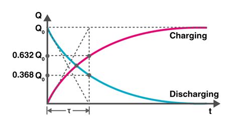
Table of Contents
Charging and Discharging Equations of a Capacitor: A Deep Dive
Capacitors, fundamental components in electronic circuits, store electrical energy in an electric field. Understanding their charging and discharging behavior is crucial for designing and analyzing various circuits. This comprehensive guide delves into the equations governing these processes, exploring the underlying physics and practical implications. We'll cover both theoretical derivations and practical considerations, ensuring a thorough grasp of capacitor dynamics.
The Fundamentals: Capacitance and Charge
Before diving into the equations, let's establish a foundational understanding of capacitance and charge. Capacitance (C) is a measure of a capacitor's ability to store charge. It's defined as the ratio of the charge (Q) stored on one plate to the potential difference (V) across the plates:
C = Q / V
The unit of capacitance is the farad (F), where 1 farad represents the ability to store 1 coulomb of charge with a potential difference of 1 volt. In simpler terms, a larger capacitance means the capacitor can store more charge for a given voltage.
Charging a Capacitor
When a capacitor is connected to a DC voltage source (like a battery) through a resistor (R), it begins to charge. The charging process isn't instantaneous; it occurs over time, governed by the following equation:
V(t) = V₀(1 - e⁻ᵗ⁄ᴿᶜ)
Where:
- V(t) is the voltage across the capacitor at time t.
- V₀ is the initial voltage of the source (the voltage the capacitor will eventually reach).
- R is the resistance in the circuit (in ohms).
- C is the capacitance (in farads).
- e is the base of the natural logarithm (approximately 2.718).
- t is the time elapsed since the charging began.
This equation describes an exponential growth. Initially, the voltage across the capacitor increases rapidly. As time goes on, the rate of increase slows down, asymptotically approaching the source voltage V₀. The term RC is known as the time constant (τ) and represents the time it takes for the capacitor to charge to approximately 63.2% of its final voltage.
Understanding the Time Constant (τ = RC)
The time constant is a crucial parameter in understanding capacitor charging behavior. It reflects the interplay between the resistance and capacitance. A larger resistance or capacitance leads to a longer time constant, meaning the capacitor charges more slowly. Conversely, smaller values of R and C result in faster charging.
-
Effect of Resistance (R): Increasing the resistance slows down the charging process because it restricts the flow of current. A higher resistance means fewer charges can flow to the capacitor plates per unit time.
-
Effect of Capacitance (C): Increasing the capacitance slows down the charging process because a larger capacitor requires more charge to reach the same voltage level.
Current During Charging
While the voltage across the capacitor is described by the above equation, the current flowing into the capacitor is given by:
I(t) = (V₀ / R) * e⁻ᵗ⁄ᴿᶜ
This shows an exponential decay. The current is highest initially, when the capacitor is empty, and gradually decreases to zero as the capacitor becomes fully charged.
Discharging a Capacitor
Once a capacitor is charged, it can be discharged by connecting it across a resistor. The voltage across the capacitor during discharge is described by:
V(t) = V₀ * e⁻ᵗ⁄ᴿᶜ
Where:
- V(t) is the voltage across the capacitor at time t.
- V₀ is the initial voltage across the capacitor (at the start of discharge).
- R is the resistance in the circuit.
- C is the capacitance.
- e is the base of the natural logarithm.
- t is the time elapsed since the discharge began.
This equation describes exponential decay. The voltage starts at V₀ and gradually decreases to zero. The time constant (RC) again plays a crucial role, determining how quickly the capacitor discharges. A larger time constant results in slower discharge, while a smaller time constant leads to faster discharge.
Current During Discharging
The current during discharge is given by:
I(t) = -(V₀ / R) * e⁻ᵗ⁄ᴿᶜ
Notice the negative sign, indicating the current flows in the opposite direction compared to charging. The current also decays exponentially, starting at a high initial value and gradually decreasing to zero as the capacitor fully discharges.
Practical Applications and Considerations
The charging and discharging equations are fundamental to various applications:
-
Timing Circuits: RC circuits are used extensively in timing applications, such as timers, oscillators, and pulse generators. The time constant provides a predictable delay, allowing for precise control of timing events.
-
Filtering: Capacitors act as filters, allowing certain frequencies to pass while blocking others. The charging and discharging characteristics determine the capacitor's response to different frequencies.
-
Energy Storage: Capacitors store energy, which can be released rapidly. This is utilized in applications like flash photography, where a capacitor stores a large amount of energy and then quickly releases it to power the flash lamp.
-
Power Supplies: Capacitors are used in power supplies to smooth out voltage fluctuations. Their ability to charge and discharge helps maintain a relatively constant voltage output.
-
Signal Processing: Capacitors are integral in signal processing circuits, shaping and filtering signals to extract desired information.
Non-Ideal Capacitors
The equations presented above assume ideal capacitors with no internal resistance or leakage current. In reality, capacitors have some internal resistance, which affects the charging and discharging times. Leakage current, a small current that flows even when the capacitor is not connected to a voltage source, also influences the capacitor's behavior over extended periods. These non-ideal effects become more significant in high-precision applications.
Advanced Concepts and Further Exploration
While the simple RC circuit provides a good introduction, more complex scenarios involve multiple capacitors and resistors, leading to more intricate charging and discharging behaviors. Techniques like Laplace transforms are frequently employed to solve these more complex circuit analyses. Additionally, the behavior of capacitors under AC conditions requires understanding concepts like impedance and reactance.
Exploring these advanced topics provides a deeper understanding of the versatility and complexities of capacitors in electronic circuits.
Conclusion
The charging and discharging equations for capacitors are essential tools for anyone working with electronic circuits. Understanding these equations, the role of the time constant, and the impact of non-ideal components allows for accurate circuit analysis, design, and troubleshooting. By mastering these concepts, engineers can effectively utilize capacitors in a wide range of applications, from simple timing circuits to complex signal processing systems. The more deeply you understand these fundamental principles, the more effectively you can harness the power and versatility of capacitors in your designs.
Latest Posts
Latest Posts
-
The Twinkling Of Stars Is Caused By
Mar 21, 2025
-
Common Denominator Of 3 4 5
Mar 21, 2025
-
Compare The Light And Dark Reactions That Occur In Plants
Mar 21, 2025
-
What Is The Weakest Intermolecular Force
Mar 21, 2025
-
Basic Building Blocks Of All Matter
Mar 21, 2025
Related Post
Thank you for visiting our website which covers about Charging And Discharging Equation Of Capacitor . We hope the information provided has been useful to you. Feel free to contact us if you have any questions or need further assistance. See you next time and don't miss to bookmark.
