Moment Of Inertia Of A T Section
Juapaving
Mar 24, 2025 · 7 min read
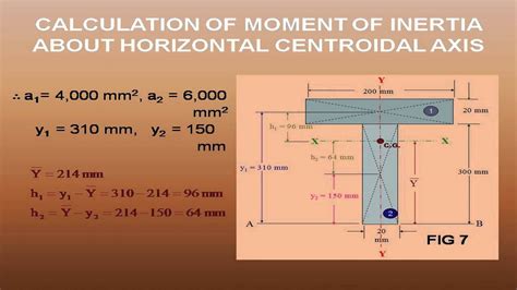
Table of Contents
Moment of Inertia of a T-Section: A Comprehensive Guide
The moment of inertia (MOI), also known as the second moment of area, is a crucial parameter in structural engineering and mechanics. It quantifies a cross-sectional area's resistance to bending or twisting. Understanding the moment of inertia, particularly for complex shapes like T-sections, is vital for accurate structural analysis and design. This comprehensive guide delves into the calculation and application of the moment of inertia of a T-section, exploring various methods and providing practical examples.
Understanding Moment of Inertia
Before tackling the complexities of a T-section, let's establish a fundamental understanding of the moment of inertia. It represents how the area of a shape is distributed relative to a chosen axis. A larger moment of inertia signifies greater resistance to bending about that axis. This is analogous to how a heavier object requires more force to rotate.
There are two principal moments of inertia:
- Second Moment of Area about the x-axis (I<sub>x</sub>): Measures resistance to bending about the horizontal x-axis.
- Second Moment of Area about the y-axis (I<sub>y</sub>): Measures resistance to bending about the vertical y-axis.
The units of moment of inertia are length to the fourth power (e.g., mm<sup>4</sup>, in<sup>4</sup>).
Calculating the Moment of Inertia of a T-Section: The Composite Method
T-sections, common in structural applications like beams and columns, aren't simple shapes. We can't directly use standard formulas. Instead, we employ the composite method. This method involves dividing the T-section into simpler, rectangular shapes, calculating the individual moments of inertia and then combining them using the parallel axis theorem.
Here's a step-by-step breakdown of the composite method:
1. Divide the T-Section: Divide the T-section into two rectangles: one representing the vertical stem and the other the horizontal flange.
2. Determine Centroids: Find the centroid of each rectangle. The centroid of a rectangle is located at its geometric center. For each rectangle, note its area (A<sub>i</sub>) and its distance (d<sub>i</sub>) from the overall centroid of the T-section.
3. Calculate Individual Moments of Inertia: For each rectangle, calculate its moment of inertia about its own centroidal axis using the standard formula:
I<sub>x,i</sub> = (1/12) * b<sub>i</sub> * h<sub>i</sub><sup>3</sup> (about the centroidal x-axis) I<sub>y,i</sub> = (1/12) * h<sub>i</sub> * b<sub>i</sub><sup>3</sup> (about the centroidal y-axis)
Where:
- b<sub>i</sub> = width of the rectangle
- h<sub>i</sub> = height of the rectangle
4. Apply the Parallel Axis Theorem: The parallel axis theorem allows us to transfer the moment of inertia from a rectangle's centroidal axis to the overall centroidal axis of the T-section. The formula is:
I<sub>x,total</sub> = Σ [I<sub>x,i</sub> + A<sub>i</sub> * d<sub>y,i</sub><sup>2</sup>] I<sub>y,total</sub> = Σ [I<sub>y,i</sub> + A<sub>i</sub> * d<sub>x,i</sub><sup>2</sup>]
Where:
- d<sub>y,i</sub> = distance between the centroid of the i-th rectangle and the overall centroid of the T-section in the y-direction.
- d<sub>x,i</sub> = distance between the centroid of the i-th rectangle and the overall centroid of the T-section in the x-direction.
5. Sum the Individual Moments of Inertia: Add the moments of inertia of all the rectangles to obtain the total moment of inertia of the T-section about the x-axis and y-axis.
Finding the Overall Centroid: Before applying the parallel axis theorem, you must determine the overall centroid of the T-section. This is done using the following formulas:
x̄ = Σ (A<sub>i</sub> * x<sub>i</sub>) / Σ A<sub>i</sub> ȳ = Σ (A<sub>i</sub> * y<sub>i</sub>) / Σ A<sub>i</sub>
Where:
- x<sub>i</sub> and y<sub>i</sub> are the coordinates of the centroid of each rectangle.
Example Calculation:
Let's illustrate with an example. Consider a T-section with the following dimensions:
- Flange: width (b<sub>f</sub>) = 150 mm, height (h<sub>f</sub>) = 50 mm
- Stem: width (b<sub>s</sub>) = 50 mm, height (h<sub>s</sub>) = 150 mm
1. Divide and Calculate Areas:
- Rectangle 1 (Flange): A<sub>1</sub> = 150 mm * 50 mm = 7500 mm²
- Rectangle 2 (Stem): A<sub>2</sub> = 50 mm * 150 mm = 7500 mm² Total Area (A) = 15000 mm²
2. Locate Centroids: We need to find the overall centroid (x̄,ȳ) using the equations above. This will involve choosing a convenient coordinate system. Let's place the origin at the bottom-left corner of the T-section.
Centroid of Rectangle 1: (x<sub>1</sub>, y<sub>1</sub>) = (75 mm, 225 mm) Centroid of Rectangle 2: (x<sub>2</sub>, y<sub>2</sub>) = (25 mm, 75 mm)
Calculating ȳ:
ȳ = [(7500 mm² * 225 mm) + (7500 mm² * 75 mm)] / (7500 mm² + 7500 mm²) = 150 mm
Calculating x̄:
x̄ = [(7500 mm² * 75 mm) + (7500 mm² * 25 mm)] / (7500 mm² + 7500 mm²) = 50 mm
3. Individual Moments of Inertia (about each rectangle's centroid):
-
Rectangle 1: I<sub>x,1</sub> = (1/12) * 150 mm * (50 mm)³ = 1562500 mm<sup>4</sup> I<sub>y,1</sub> = (1/12) * 50 mm * (150 mm)³ = 8437500 mm<sup>4</sup>
-
Rectangle 2: I<sub>x,2</sub> = (1/12) * 50 mm * (150 mm)³ = 8437500 mm<sup>4</sup> I<sub>y,2</sub> = (1/12) * 150 mm * (50 mm)³ = 1562500 mm<sup>4</sup>
4. Apply Parallel Axis Theorem:
Now we calculate the distances from each rectangle's centroid to the overall centroid:
- Rectangle 1: d<sub>x,1</sub> = 75 mm - 50 mm = 25 mm; d<sub>y,1</sub> = 225 mm - 150 mm = 75 mm
- Rectangle 2: d<sub>x,2</sub> = 25 mm - 50 mm = -25 mm; d<sub>y,2</sub> = 75 mm - 150 mm = -75 mm
Now, we apply the parallel axis theorem:
I<sub>x,total</sub> = [1562500 mm<sup>4</sup> + 7500 mm² * (75 mm)²] + [8437500 mm<sup>4</sup> + 7500 mm² * (-75 mm)²] = 137812500 mm<sup>4</sup> I<sub>y,total</sub> = [8437500 mm<sup>4</sup> + 7500 mm² * (25 mm)²] + [1562500 mm<sup>4</sup> + 7500 mm² * (-25 mm)²] = 22031250 mm<sup>4</sup>
Therefore, the moment of inertia of this T-section about the x-axis is 137,812,500 mm<sup>4</sup>, and about the y-axis is 22,031,250 mm<sup>4</sup>.
Applications of Moment of Inertia of T-Sections
The moment of inertia of a T-section is crucial in various structural engineering applications:
-
Beam Design: Calculating deflection and stresses in beams subjected to bending loads. A higher moment of inertia indicates greater stiffness and resistance to deflection.
-
Column Design: Determining the buckling capacity of columns under compressive loads. The moment of inertia influences the column's stability.
-
Section Modulus: The section modulus (S = I/c, where c is the distance from the neutral axis to the outermost fiber) is directly related to the moment of inertia and is used to calculate bending stresses.
-
Torsional Analysis: While primarily used for bending, the moment of inertia also plays a role in torsional analysis for certain types of T-section designs.
-
Finite Element Analysis (FEA): The moment of inertia is a key input parameter in FEA simulations for accurate structural modeling and analysis.
Software and Tools for Calculation
While manual calculations are valuable for understanding the underlying principles, software significantly simplifies the process, especially for complex sections. Various structural engineering software packages offer tools to automatically calculate the moment of inertia of any cross-section, including T-sections. These programs often incorporate advanced features like automatic centroid determination and handling of more intricate geometries.
Conclusion
The moment of inertia of a T-section is a critical parameter in structural analysis and design. The composite method, along with the parallel axis theorem, provides a systematic approach to calculating it. Mastering this calculation is essential for structural engineers to ensure the safety and efficiency of their designs. Remember to carefully define your coordinate system and meticulously follow each step in the calculation to obtain accurate results. While manual calculation is instructive, leveraging engineering software can significantly improve efficiency, especially in complex projects. The ability to accurately determine the moment of inertia is foundational to the successful design and analysis of structures employing T-sections.
Latest Posts
Latest Posts
-
What Is The Division Of Cytoplasm Called
Mar 25, 2025
-
3 1 8 As A Decimal
Mar 25, 2025
-
What Is A Factor Of 5
Mar 25, 2025
-
List Three Similarities Between Dna And Rna
Mar 25, 2025
-
Light Wave Is Longitudinal Or Transverse
Mar 25, 2025
Related Post
Thank you for visiting our website which covers about Moment Of Inertia Of A T Section . We hope the information provided has been useful to you. Feel free to contact us if you have any questions or need further assistance. See you next time and don't miss to bookmark.
