How Voltmeter Is Connected In A Circuit
Juapaving
Mar 29, 2025 · 6 min read
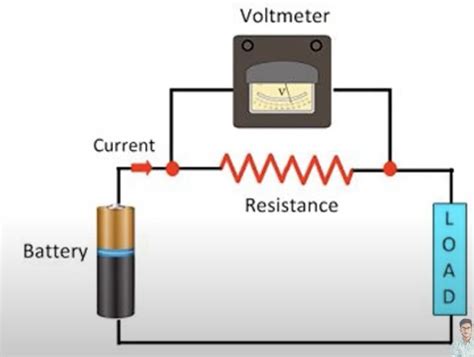
Table of Contents
How a Voltmeter is Connected in a Circuit: A Comprehensive Guide
Measuring voltage is fundamental in electronics and electrical engineering. Understanding how to correctly connect a voltmeter to a circuit is crucial for accurate readings and, importantly, for preventing damage to your equipment and yourself. This comprehensive guide will delve into the intricacies of voltmeter connection, covering various circuit configurations and providing practical tips for safe and effective measurements.
Understanding Voltage and its Measurement
Before diving into connection techniques, let's briefly revisit the concept of voltage. Voltage, also known as electric potential difference, is the electrical pressure that pushes charged particles (electrons) through a conductor. It's measured in volts (V) and represents the energy difference between two points in a circuit. A voltmeter is the instrument used to measure this potential difference.
The Voltmeter: A Key Measurement Tool
Voltmeters are designed to measure the voltage across a component or a section of a circuit. Unlike ammeters, which are connected in series, voltmeters are always connected in parallel. This parallel connection allows the voltmeter to measure the potential difference between two points without significantly affecting the circuit's operation. The internal resistance of a good voltmeter is very high, minimizing the current drawn from the circuit under test.
Connecting a Voltmeter: Parallel Connection Explained
The core principle of voltmeter connection is parallelism. This means the voltmeter's probes are connected to the two points in the circuit across which you want to measure the voltage. Imagine the voltmeter as a tiny detour for the electrons; they flow around the voltmeter, not through it. This parallel connection ensures that the voltmeter only measures the voltage, not substantially alters the current flow in the circuit.
Step-by-Step Guide to Parallel Connection
-
Identify the Points of Measurement: Determine the two points in the circuit between which you want to measure the voltage. This could be across a resistor, a capacitor, a battery, or any other component.
-
Set the Voltmeter Range: Before connecting the probes, set the voltmeter to an appropriate voltage range. Always start with a range higher than the expected voltage. This prevents overloading the voltmeter and obtaining inaccurate readings. If you're unsure of the voltage, it's always safer to begin with the highest range and then adjust downwards.
-
Connect the Probes: Carefully connect the voltmeter's probes to the chosen points. The positive (+) probe (usually red) is connected to the point with higher potential, while the negative (-) probe (usually black) is connected to the point with lower potential. Accurate polarity is critical for correct readings. Reversing the probes will result in a negative reading or, in some meters, an error indication.
-
Observe the Reading: Once the probes are securely connected, observe the voltmeter's display. The reading indicates the voltage difference between the two points.
-
Disconnect the Probes: After taking the reading, disconnect the probes from the circuit. Leaving the probes connected unnecessarily can drain the battery of the circuit under test or even damage the voltmeter.
Connecting a Voltmeter in Different Circuit Configurations
The parallel connection principle remains constant across various circuit configurations. However, the specific points of connection will vary depending on what you want to measure. Let’s examine some common scenarios:
1. Measuring Voltage Across a Resistor
To measure the voltage across a resistor, connect the positive probe to one end of the resistor and the negative probe to the other end. This will directly measure the voltage drop across the resistor. This voltage drop is directly proportional to the current flowing through the resistor and its resistance (Ohm's Law: V = IR).
2. Measuring Voltage Across a Battery
Measuring the voltage of a battery involves connecting the positive probe to the battery's positive terminal and the negative probe to the negative terminal. This measurement provides the battery's terminal voltage, which may slightly differ from its open-circuit voltage due to internal resistance.
3. Measuring Voltage Across a Capacitor
Measuring voltage across a capacitor requires connecting the probes across the capacitor's terminals. Remember that capacitors store energy, so be cautious when handling charged capacitors. Discharging the capacitor before measurement is a vital safety precaution.
4. Measuring Voltage in Series Circuits
In a series circuit, the voltage across individual components adds up to the total voltage supplied by the source. To measure the voltage across a specific component in a series circuit, connect the voltmeter's probes across the terminals of that component.
5. Measuring Voltage in Parallel Circuits
In a parallel circuit, the voltage across each branch is the same as the source voltage. To measure the voltage across a particular branch, connect the probes across the terminals of that branch. Each branch will have the same voltage as the source, irrespective of the individual resistances in each branch.
Safety Precautions When Using a Voltmeter
Working with electricity always requires caution. Here are some vital safety precautions when using a voltmeter:
- Always use the correct voltage range: Selecting a range too low can damage the voltmeter.
- Never touch the probes while the voltmeter is connected to a live circuit: This can lead to electric shock.
- Ensure the voltmeter is appropriately rated for the voltage being measured: Using a voltmeter with a lower voltage rating than the voltage being measured is extremely dangerous.
- Disconnect the probes before making adjustments to the circuit or changing voltage ranges: This minimizes the risk of accidental shock or damage.
- Inspect the probes for damage before each use: Damaged probes can lead to inaccurate readings or electrical shocks.
- Always work with circuits that are properly insulated and grounded: This prevents accidental contact with live wires and reduces the risk of electric shock.
- Understand the circuit before making any measurements: Knowing the circuit's configuration and anticipated voltages will help to prevent mistakes and ensure safe operation.
- Use insulated tools and work in a well-lit area: This minimizes the risk of accidents.
- If you are unsure about any aspect of using a voltmeter, consult a qualified electrician: Safety should always be your top priority.
Troubleshooting Common Voltmeter Issues
Sometimes, you might encounter problems when using a voltmeter. Here are some common issues and their possible solutions:
- Inaccurate Readings: Check the voltmeter's calibration, ensure proper probe connection, and verify the selected range. A faulty voltmeter may need replacement or repair.
- No Reading: Check the battery in the voltmeter, ensure the probes are securely connected, and verify that the circuit is powered. A blown fuse in the voltmeter might also be the culprit.
- Erratic Readings: This could indicate a faulty voltmeter, a problem with the circuit under test (e.g., loose connections), or interference from other electrical devices.
Conclusion: Mastering Voltmeter Connections for Accurate Measurements
Correctly connecting a voltmeter is paramount for obtaining reliable voltage readings. This involves understanding the principles of parallel connection, choosing the appropriate voltage range, and adhering to strict safety precautions. By following the steps outlined in this guide and prioritizing safety, you can confidently use a voltmeter to measure voltage in various circuits, facilitating a deeper understanding of electrical systems and enhancing your troubleshooting capabilities. Remember that practice makes perfect; repeated use and careful observation will build your expertise and confidence in this fundamental electrical measurement technique.
Latest Posts
Latest Posts
-
Is Calcium Hydroxide A Base Or Acid
Mar 31, 2025
-
The Ultimate Source Of Energy From Fossil Fuels Is The
Mar 31, 2025
-
Dna Is A Polymer Made From What Monomer Units
Mar 31, 2025
-
What Are All The Multiples Of 8
Mar 31, 2025
-
Is Wax Melting A Physical Change
Mar 31, 2025
Related Post
Thank you for visiting our website which covers about How Voltmeter Is Connected In A Circuit . We hope the information provided has been useful to you. Feel free to contact us if you have any questions or need further assistance. See you next time and don't miss to bookmark.
