Difference Between Series And Parallel Circuits Table
Juapaving
Mar 24, 2025 · 6 min read
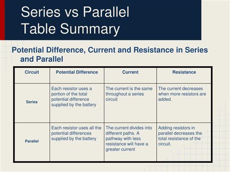
Table of Contents
Series vs. Parallel Circuits: A Comprehensive Comparison
Understanding the fundamental differences between series and parallel circuits is crucial for anyone studying electricity or working with electrical systems. While both involve connecting components to a power source, their behavior and characteristics differ significantly. This article provides a detailed comparison of series and parallel circuits, highlighting their key distinctions through explanations, illustrations, and a comprehensive table. We'll delve into voltage, current, resistance, and power calculations, enabling you to confidently analyze and design circuits.
Key Differences: Series vs. Parallel Circuits
The most significant difference lies in how the components are connected:
- Series Circuit: Components are connected end-to-end, forming a single path for current flow. Imagine a single road where all traffic must travel along the same route.
- Parallel Circuit: Components are connected across each other, providing multiple paths for current flow. Think of multiple roads branching off from a highway, allowing traffic to take different routes.
This fundamental difference leads to contrasting characteristics in terms of voltage, current, resistance, and power distribution.
Voltage in Series and Parallel Circuits
Series Circuits: In a series circuit, the total voltage is the sum of the individual voltage drops across each component. This is a direct application of Kirchhoff's Voltage Law (KVL), which states that the sum of voltage drops around a closed loop must equal zero. Therefore, if you have three resistors (R1, R2, R3) with voltage drops V1, V2, and V3 respectively, the total voltage (Vt) is:
Vt = V1 + V2 + V3
Parallel Circuits: In a parallel circuit, the voltage across each component is the same and equal to the source voltage. This is because each component is connected directly across the terminals of the voltage source. Therefore, if the source voltage is Vs, then the voltage across each component (V1, V2, V3) is:
V1 = V2 = V3 = Vs
Current in Series and Parallel Circuits
Series Circuits: In a series circuit, the current is the same throughout the entire circuit. This is because there's only one path for the current to flow. If the current is I, then the current through each component (I1, I2, I3) is:
I = I1 = I2 = I3
Parallel Circuits: In a parallel circuit, the total current is the sum of the individual currents flowing through each branch. This is a direct consequence of Kirchhoff's Current Law (KCL), which states that the sum of currents entering a node must equal the sum of currents leaving the node. Therefore, if the branch currents are I1, I2, and I3, the total current (It) is:
It = I1 + I2 + I3
Resistance in Series and Parallel Circuits
Series Circuits: In a series circuit, the total resistance is the sum of the individual resistances. This makes intuitive sense, as the current must overcome the resistance of each component sequentially. For resistors R1, R2, and R3, the total resistance (Rt) is:
Rt = R1 + R2 + R3
Parallel Circuits: In a parallel circuit, the total resistance is less than the smallest individual resistance. This is because the multiple paths provide an easier route for current flow. The reciprocal of the total resistance (1/Rt) is equal to the sum of the reciprocals of the individual resistances:
1/Rt = 1/R1 + 1/R2 + 1/R3
Power in Series and Parallel Circuits
Series Circuits: The power dissipated in each component of a series circuit is calculated using the formula P = I²R, where I is the same for all components. The total power dissipated is the sum of the power dissipated in each component.
Parallel Circuits: The power dissipated in each component of a parallel circuit is calculated using the formula P = V² / R, where V is the same for all components. The total power dissipated is, again, the sum of the power dissipated in each component.
Practical Applications
The choice between a series and parallel circuit depends entirely on the desired outcome and the characteristics of the components.
Series circuits are often used in simple applications where a single path for current is sufficient. For instance, Christmas lights (older style incandescent bulbs) are often wired in series. A break in any single bulb interrupts the current flow for the entire string.
Parallel circuits are widely used in most household wiring systems. Each appliance is connected in parallel, ensuring that a malfunctioning appliance doesn't affect the operation of others. Furthermore, parallel circuits offer more flexibility and allow for varying loads.
Advantages and Disadvantages
| Feature | Series Circuit | Parallel Circuit |
|---|---|---|
| Voltage | Voltage is divided among components. | Voltage is the same across all components. |
| Current | Current is the same throughout the circuit. | Current is divided among branches. |
| Resistance | Total resistance is the sum of individual resistances. | Total resistance is less than the smallest resistance. |
| Power | Power is calculated using I²R for each component. | Power is calculated using V²/R for each component. |
| Advantages | Simple to design and understand. | Each component operates independently; failure of one doesn't affect others. |
| Disadvantages | A single faulty component can disrupt the entire circuit; voltage drop across each component can be problematic for sensitive devices. | More complex wiring; potentially higher current draw. |
Troubleshooting Series and Parallel Circuits
Troubleshooting these circuits involves systematically identifying the source of any malfunction.
Series Circuits: In a series circuit, if a component fails (e.g., a bulb burns out or a resistor breaks), the entire circuit will stop working because the current flow is interrupted. Troubleshooting involves checking each component individually to identify the faulty one.
Parallel Circuits: In a parallel circuit, if a component fails, the other components will continue to operate normally because the current can still flow through the other branches. Troubleshooting in this case involves isolating the faulty branch.
Advanced Concepts and Considerations
The discussion above primarily focuses on simple circuits with resistive components. However, real-world circuits often incorporate other components such as capacitors and inductors, which introduce more complex behavior and require a deeper understanding of AC circuits and impedance.
Conclusion: Choosing the Right Circuit
The decision to use a series or parallel circuit is a critical design choice. Series circuits are simple but vulnerable to failures, while parallel circuits provide redundancy and independent operation of components but are more complex. The specific application, power requirements, and desired behavior will dictate the appropriate choice. By understanding the fundamental differences and applying the principles discussed in this article, you can effectively analyze, design, and troubleshoot both series and parallel circuits. Remember to always prioritize safety when working with electricity. This comprehensive comparison provides a solid foundation for anyone venturing into the world of electronics and circuit design. Understanding these core concepts is crucial for further exploration of more complex electrical systems and applications.
Latest Posts
Latest Posts
-
How Much Is 18 Cm In Inches
Mar 26, 2025
-
Oxidation Reduction Reactions In Cellular Respiration
Mar 26, 2025
-
What Direction Does Dna Polymerase Read
Mar 26, 2025
-
What Is 25 Cm In Inches
Mar 26, 2025
-
Which Of The Following Statements Describes The Process Of Globalization
Mar 26, 2025
Related Post
Thank you for visiting our website which covers about Difference Between Series And Parallel Circuits Table . We hope the information provided has been useful to you. Feel free to contact us if you have any questions or need further assistance. See you next time and don't miss to bookmark.
