Circuit Diagram Full Wave Center Tap Rectifier Unregulated
Juapaving
Mar 19, 2025 · 5 min read
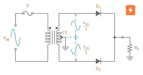
Table of Contents
Circuit Diagram: Full Wave Center-Tap Rectifier (Unregulated) – A Deep Dive
The full-wave center-tap rectifier is a fundamental circuit in electronics, efficiently converting alternating current (AC) to pulsating direct current (DC). Understanding its operation, advantages, and limitations is crucial for anyone working with power supplies and rectification. This comprehensive guide delves into the specifics of this unregulated rectifier, exploring its circuit diagram, working principle, advantages, disadvantages, and applications. We'll also discuss crucial design considerations and potential improvements.
Understanding the Basics: AC to DC Conversion
Before diving into the intricacies of the full-wave center-tap rectifier, let's establish the fundamental concept of AC-to-DC conversion, or rectification. AC voltage, characterized by its sinusoidal waveform, constantly changes polarity. Rectifiers are electronic circuits that convert this alternating current into a unidirectional current, although the output may not be a perfectly smooth DC.
Several types of rectifiers exist, each with its own characteristics and applications. The full-wave center-tap rectifier is one of the most common, offering several advantages over its half-wave counterpart.
The Full-Wave Center-Tap Rectifier: Circuit Diagram and Working Principle
The heart of this rectifier lies in its transformer with a center-tapped secondary winding. This center tap provides a crucial reference point for the rectification process. Let's examine a typical circuit diagram:
                                    +-----------------+
                                    |                 |
                                    |    AC Input     |----/\/\/\/\----|
                                    |                 |       Rload     |----(Output) DC
                                    +--------+---------+-----------------+
                                            |
                                            |
                                   +--------+--------+
                                   |                |
                                   |     Diode D1    |
                                   +--------+--------+
                                            |
                                            |
                                            |  Center Tap
                                            |
                                   +--------+--------+
                                   |                |
                                   |     Diode D2    |
                                   +--------+--------+
                                            |
                                            |
                                    +--------+---------+
                                    |                 |
                                    |    AC Input     |----/\/\/\/\----|
                                    |                 |       Rload     |----(Output) DC
                                    +-----------------+
Here's how it works:
-
Positive Half-Cycle: During the positive half-cycle of the AC input, the top of the secondary winding becomes positive relative to the center tap. Diode D1 is forward-biased (conducting), allowing current to flow through D1, the load resistor (Rload), and back to the center tap.
-
Negative Half-Cycle: During the negative half-cycle, the bottom of the secondary winding becomes negative relative to the center tap. Diode D2 is now forward-biased, allowing current to flow through D2, the load resistor (Rload), and back to the center tap.
Key Observation: Notice that current flows through the load resistor in the same direction during both half-cycles. This is the essence of full-wave rectification. While the current isn't smooth, it's unidirectional.
Understanding the Output Waveform
The output waveform of a full-wave center-tap rectifier isn't a pure DC signal; instead, it's a pulsating DC waveform. It consists of the positive portions of both half-cycles of the AC input, resulting in a frequency twice that of the input AC. This pulsating nature often requires further filtering (smoothing) to produce a more stable DC voltage.
Advantages of the Full-Wave Center-Tap Rectifier
-
Higher Efficiency: Compared to a half-wave rectifier, the full-wave center-tap rectifier utilizes both halves of the AC input waveform, resulting in higher average DC output voltage and improved efficiency.
-
Reduced Ripple: Although still present, the ripple voltage (the fluctuation in the DC output) is significantly reduced compared to a half-wave rectifier, due to the higher frequency of the pulsating DC output. This means a smoother DC voltage at the output.
-
Simpler Design (in some cases): For lower voltage applications, the center-tap rectifier might be simpler to implement than a bridge rectifier as it only requires two diodes.
Disadvantages of the Full-Wave Center-Tap Rectifier
-
Requires a Center-Tapped Transformer: This is a significant drawback, as center-tapped transformers are generally more expensive and bulky than non-center-tapped transformers.
-
Voltage Limitation: The maximum output DC voltage is limited to half the peak secondary voltage of the transformer.
-
Higher Voltage Drop: The voltage drop across each diode further reduces the output DC voltage.
Applications
The full-wave center-tap rectifier finds application in various low-power DC power supply designs, particularly where the cost and size of a center-tapped transformer are not major concerns. Examples include:
- Simple DC power supplies: powering small electronic devices.
- Battery chargers: charging low-voltage batteries.
- Educational purposes: demonstrating basic rectification principles.
Design Considerations
Several crucial factors must be considered when designing a full-wave center-tap rectifier:
-
Transformer Selection: Choosing the appropriate transformer is critical. The transformer's secondary voltage, current rating, and center tap are all important parameters.
-
Diode Selection: Diodes must have sufficient voltage and current ratings to handle the expected input voltage and current. The reverse recovery time of the diodes is also important to minimize losses.
-
Filter Design: To smooth the pulsating DC output, a filter circuit (often using capacitors and inductors) is almost always necessary. The capacitor's value significantly impacts the ripple voltage.
-
Load Characteristics: The nature of the load (resistive, capacitive, inductive) affects the design. A purely resistive load is the simplest scenario, while capacitive or inductive loads require more sophisticated filter designs.
Improving the Rectifier's Performance: Adding a Filter
As mentioned, the pulsating DC output of the rectifier is often unsuitable for many applications. Adding a filter circuit significantly improves the quality of the DC output by reducing the ripple voltage. The most common type of filter is a capacitor filter placed across the output. A larger capacitor will reduce the ripple voltage significantly, but it also increases the size and cost. More complex filter circuits, like pi filters (using capacitors and an inductor), can further reduce the ripple.
Conclusion
The full-wave center-tap rectifier is a fundamental circuit in electronics, effectively converting AC to pulsating DC. While it offers advantages like higher efficiency and reduced ripple compared to a half-wave rectifier, its requirement for a center-tapped transformer presents a significant drawback. Understanding the circuit's operation, advantages, disadvantages, and crucial design considerations is vital for implementing it correctly and effectively in various applications. The addition of a filter circuit is crucial to obtaining a smooth DC output. Careful selection of components, considering the load characteristics, and appropriately designing the filter circuit are essential for optimal performance. Remember to always prioritize safety when working with electrical circuits.
Latest Posts
Latest Posts
-
What Is The Square Root Of 900
Mar 20, 2025
-
What Does Sound Travel Fastest Through
Mar 20, 2025
-
What Percent Of 50 Is 10
Mar 20, 2025
-
Whats The Square Root Of 10
Mar 20, 2025
-
What Is Si Unit Of Distance
Mar 20, 2025
Related Post
Thank you for visiting our website which covers about Circuit Diagram Full Wave Center Tap Rectifier Unregulated . We hope the information provided has been useful to you. Feel free to contact us if you have any questions or need further assistance. See you next time and don't miss to bookmark.
