Moment Of Inertia Of Rectangular Plate
Juapaving
Mar 09, 2025 · 6 min read
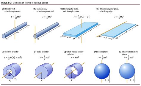
Table of Contents
Moment of Inertia of a Rectangular Plate: A Comprehensive Guide
The moment of inertia, a crucial concept in physics and engineering, describes an object's resistance to changes in its rotation. Understanding the moment of inertia is vital for analyzing the dynamics of rotating bodies, from simple pendulums to complex machinery. This comprehensive guide delves into the calculation of the moment of inertia of a rectangular plate, exploring various scenarios and providing detailed explanations to solidify your understanding.
Understanding Moment of Inertia
Before we dive into the specifics of rectangular plates, let's establish a foundational understanding of moment of inertia. It's a measure of how difficult it is to change the rotational speed of an object. A larger moment of inertia indicates a greater resistance to angular acceleration. Unlike mass, which is a scalar quantity, the moment of inertia is a tensor, meaning its value depends on the axis of rotation. This means the moment of inertia of a rectangular plate will differ depending on whether we're rotating it about its center, an edge, or a diagonal.
The formula for the moment of inertia (I) of a continuous mass distribution is:
I = ∫ r² dm
where:
- I represents the moment of inertia
- r is the perpendicular distance from the axis of rotation to the infinitesimal mass element dm
- ∫ denotes integration over the entire mass distribution
This formula states that the moment of inertia is the sum of the products of each infinitesimal mass element and the square of its distance from the axis of rotation. For simple shapes like rectangular plates, this integral can be solved analytically, leading to specific formulas we'll explore below.
Moment of Inertia of a Rectangular Plate: Different Axes of Rotation
The moment of inertia of a rectangular plate varies significantly based on the chosen axis of rotation. Let's examine the most common scenarios:
1. Axis of Rotation through the Center of Mass, Parallel to a Side
Consider a rectangular plate with mass M, width b, and height h. If we rotate it about an axis passing through its center of mass and parallel to one of its sides (let's say the side of length b), the moment of inertia (I<sub>x</sub>) is given by:
I<sub>x</sub> = (1/12)Mh²
This formula assumes a uniformly distributed mass across the plate. Notice that the moment of inertia depends only on the mass and the square of the height, which is perpendicular to the axis of rotation. The width b doesn't appear in this equation because the axis of rotation is parallel to the side of length b.
2. Axis of Rotation through the Center of Mass, Perpendicular to the Plate
If we rotate the rectangular plate about an axis perpendicular to its plane and passing through its center of mass, the moment of inertia (I<sub>z</sub>) is given by:
I<sub>z</sub> = (1/12)M(b² + h²)
This formula is a direct consequence of the parallel axis theorem (which we'll discuss later). In this case, the moment of inertia depends on both the width and height of the rectangle. This axis is often referred to as the polar axis.
3. Axis of Rotation along an Edge
Rotating the plate about an axis along one of its edges (let's say the edge of length b) results in a different moment of inertia. Using the parallel axis theorem, we can calculate this as:
I<sub>edge</sub> = (1/3)Mh²
This moment of inertia is significantly larger than when rotating about the center of mass parallel to the side, reflecting the increased distance of mass elements from the axis of rotation.
4. Axis of Rotation through a Corner
The most complex scenario involves rotating the plate around an axis passing through one of its corners. This requires a more intricate calculation using integration or applying the parallel axis theorem multiple times. The resulting moment of inertia (I<sub>corner</sub>) is:
I<sub>corner</sub> = (1/3)M(b² + h²)
This formula highlights that the moment of inertia is significantly greater when rotating about a corner than around the center of mass.
The Parallel Axis Theorem: A Powerful Tool
The parallel axis theorem is an invaluable tool for calculating moments of inertia about axes that are parallel to an axis passing through the center of mass. It states that the moment of inertia (I) about any axis is equal to the moment of inertia (I<sub>cm</sub>) about a parallel axis through the center of mass plus the product of the mass (M) and the square of the distance (d) between the two axes. Mathematically:
I = I<sub>cm</sub> + Md²
Using this theorem, we can derive the formulas for moments of inertia about axes along edges or through corners from the simpler cases we've already examined. For example, the formula for I<sub>edge</sub> is derived by applying the parallel axis theorem to I<sub>x</sub>, using d = h/2.
Applications of Moment of Inertia of a Rectangular Plate
Understanding the moment of inertia of a rectangular plate has numerous practical applications in various fields:
- Mechanical Engineering: Designing rotating components like gears, flywheels, and shafts. The moment of inertia is crucial for determining their angular acceleration and rotational kinetic energy.
- Civil Engineering: Analyzing the stability of structures subjected to wind loads or seismic activity. The moment of inertia influences the structural stiffness and resistance to bending.
- Aerospace Engineering: Calculating the stability and maneuverability of aircraft and spacecraft. The moment of inertia affects how easily these vehicles can change their orientation.
- Robotics: Designing and controlling robotic arms and manipulators. The moment of inertia affects the speed and precision of movements.
Beyond the Basics: Non-Uniform Mass Distribution and Complex Shapes
The formulas provided earlier assume a uniform mass distribution across the rectangular plate. In real-world scenarios, this might not always be the case. If the mass distribution is non-uniform, the calculation of the moment of inertia becomes more complex and often requires numerical integration techniques. Similarly, for more intricate shapes derived from rectangular plates (e.g., plates with cutouts), the calculation can also become substantially more challenging. These scenarios often necessitate the use of computational tools like Finite Element Analysis (FEA) software.
Conclusion: Mastering the Moment of Inertia
Understanding the moment of inertia of a rectangular plate is fundamental to various engineering and physics disciplines. By mastering the formulas and applying the parallel axis theorem, you can accurately analyze the rotational dynamics of a wide range of systems. Remember to always consider the axis of rotation carefully, as this significantly influences the calculated value. While the examples discussed here focus on uniformly distributed mass, keep in mind the complexities that arise with non-uniform mass distributions and more intricate shapes. With a solid grasp of these concepts, you can confidently tackle more advanced problems in rotational mechanics. The journey to mastering moment of inertia is an iterative process, requiring continuous practice and a deep understanding of the underlying principles. This guide serves as a comprehensive starting point on your path to becoming proficient in this crucial area of physics and engineering.
Latest Posts
Latest Posts
-
The Capacity To Do Work Is Known As
Mar 09, 2025
-
What Is Prime Factorization Of 70
Mar 09, 2025
-
What Is A Factor Of 93
Mar 09, 2025
-
How Is Photosynthesis And Cellular Respiration Connected
Mar 09, 2025
-
Is Every Real Number A Irrational Number
Mar 09, 2025
Related Post
Thank you for visiting our website which covers about Moment Of Inertia Of Rectangular Plate . We hope the information provided has been useful to you. Feel free to contact us if you have any questions or need further assistance. See you next time and don't miss to bookmark.
