Moment Of Inertia For A Rod
Juapaving
Mar 20, 2025 · 6 min read
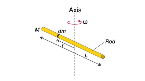
Table of Contents
Moment of Inertia for a Rod: A Comprehensive Guide
The moment of inertia, a crucial concept in physics and engineering, describes an object's resistance to changes in its rotation. Understanding this concept is vital for analyzing rotational motion, from the simple swing of a pendulum to the complex dynamics of a spinning turbine. This article delves into the calculation of the moment of inertia for a rod, exploring various scenarios and providing a comprehensive understanding of the underlying principles.
Understanding Moment of Inertia
Before diving into the specifics of a rod, let's establish a fundamental understanding of moment of inertia (often denoted as I). It's the rotational analog of mass in linear motion. Just as mass resists changes in linear velocity, moment of inertia resists changes in angular velocity. The greater the moment of inertia, the more difficult it is to change the object's rotational speed.
The moment of inertia depends on two factors:
- Mass (m): A more massive object inherently resists changes in rotation more strongly.
- Distribution of Mass (r): The distribution of mass relative to the axis of rotation is critical. Mass concentrated farther from the axis contributes more significantly to the moment of inertia than mass closer to the axis. This is why the formula includes the square of the distance (r²).
Mathematically, the moment of inertia is expressed as the sum of the products of each particle's mass and the square of its distance from the axis of rotation:
I = Σ mᵢrᵢ²
where:
- I is the moment of inertia
- mᵢ is the mass of the ith particle
- rᵢ is the distance of the ith particle from the axis of rotation
For continuous objects like a rod, this summation becomes an integral.
Calculating Moment of Inertia for a Thin Rod
Let's consider a thin, uniform rod of length L and total mass M. We'll examine the moment of inertia for two different axes of rotation:
1. Axis of Rotation Perpendicular to the Rod and Passing Through its Center
This is the most common scenario. Imagine the rod lying horizontally, and the axis of rotation passing vertically through its midpoint. To calculate the moment of inertia, we can consider the rod as a collection of infinitesimally small mass elements, dm.
First, we need to relate dm to the linear mass density (λ) of the rod:
λ = M/L
Therefore, dm = λdx, where dx is a small length element along the rod. The distance of dm from the center of the rod is x. Using the integral form of the moment of inertia formula:
I = ∫ r² dm = ∫<sub>-L/2</sub><sup>L/2</sup> x² λ dx
Solving this integral, we get:
I = (1/12)ML²
This is the crucial formula for the moment of inertia of a thin rod about an axis perpendicular to the rod and passing through its center.
2. Axis of Rotation Perpendicular to the Rod and Passing Through One End
Now, let's consider the axis of rotation passing through one end of the rod. The process is similar, but the limits of integration change. The distance of dm from the end of the rod is now simply x, and the integration limits are from 0 to L:
I = ∫ r² dm = ∫<sub>0</sub><sup>L</sup> x² λ dx
Solving this integral, we get:
I = (1/3)ML²
Notice that the moment of inertia is greater in this case. This is because the mass is distributed further from the axis of rotation, increasing the resistance to angular acceleration.
Parallel Axis Theorem
The parallel axis theorem provides a powerful shortcut for calculating the moment of inertia about an axis parallel to an axis through the center of mass. It states that the moment of inertia (I) about any axis parallel to an axis through the center of mass is equal to the moment of inertia about the center of mass (I<sub>cm</sub>) plus the product of the total mass (M) and the square of the distance (d) between the two axes:
I = I<sub>cm</sub> + Md²
For example, to calculate the moment of inertia of a rod about an axis perpendicular to it and passing through one end (as calculated above), we can use the parallel axis theorem:
- I<sub>cm</sub> = (1/12)ML² (moment of inertia about the center)
- d = L/2 (distance between the two axes)
Therefore:
I = (1/12)ML² + M(L/2)² = (1/3)ML²
This confirms the result obtained earlier through direct integration. The parallel axis theorem is a significant time-saver for various calculations.
Moment of Inertia for Rods of Different Shapes and Cross-Sections
While the above calculations are for a thin, uniform rod, the principles extend to rods with different shapes and cross-sections. However, the calculations become more complex. For example:
Non-Uniform Rods
If the rod has a non-uniform mass distribution, the linear mass density (λ) becomes a function of x, requiring a more intricate integral calculation. The specific form of λ will dictate the final moment of inertia.
Thick Rods
For thicker rods, the moment of inertia will be different. The cross-sectional shape influences the distribution of mass and therefore impacts the calculation. This might involve considering a double integral if the cross-sectional area is not simple.
Rods with Complex Shapes
For rods with intricate shapes or varying cross-sections, numerical methods or advanced techniques might be needed. Software packages specializing in computational mechanics can handle such complexities.
Applications of Moment of Inertia for Rods
The concept of moment of inertia for rods has wide-ranging applications in various fields, including:
-
Mechanical Engineering: Designing rotating machinery, such as shafts, gears, and flywheels, requires precise calculation of moment of inertia to ensure structural integrity and efficient performance. Understanding how the moment of inertia affects angular acceleration and torque is crucial in optimizing designs.
-
Physics: In numerous physics experiments and analyses, including pendulums, physical pendulums, and rotational motion experiments, the calculation of moment of inertia for rods is vital. The period of oscillation of a physical pendulum is directly related to its moment of inertia.
-
Aerospace Engineering: Designing aircraft and spacecraft involves analyzing rotational dynamics, where the moment of inertia of various components (including rod-like structures) plays a crucial role in stability and maneuverability calculations. This is particularly important in the control and stability of rockets and satellites.
-
Robotics: The design and control of robotic arms and manipulators rely heavily on the precise calculation of moment of inertia for their constituent components, ensuring smooth and precise movements.
Conclusion
Understanding the moment of inertia for a rod is fundamental to grasping rotational dynamics. This article has explored the derivation of the moment of inertia for a thin, uniform rod about different axes, demonstrated the application of the parallel axis theorem, and briefly touched upon the complexities involved with non-uniform or complex rod shapes. The principles discussed here form the basis for more advanced analyses in mechanical engineering, physics, and related disciplines. Mastering this concept lays a strong foundation for further exploration in the fascinating world of rotational motion. Remember that while this guide provides a robust foundation, consulting more advanced texts and employing computational tools can be beneficial for more complex scenarios.
Latest Posts
Latest Posts
-
3 1 4 As Improper Fraction
May 09, 2025
-
What Organelles Involved In Protein Synthesis
May 09, 2025
-
How Many Feet Is 25 Centimeters
May 09, 2025
-
Size Chart In Cm And Inches
May 09, 2025
-
How Heat Is Different From Temperature
May 09, 2025
Related Post
Thank you for visiting our website which covers about Moment Of Inertia For A Rod . We hope the information provided has been useful to you. Feel free to contact us if you have any questions or need further assistance. See you next time and don't miss to bookmark.