How Is An Ammeter Connected Into A Circuit
Juapaving
Mar 22, 2025 · 6 min read
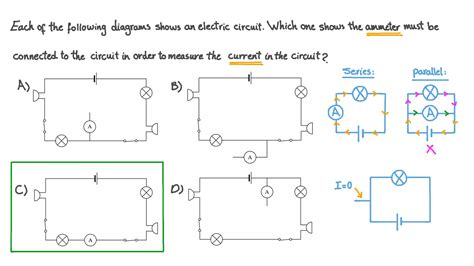
Table of Contents
How Is An Ammeter Connected Into a Circuit? A Comprehensive Guide
Measuring current in an electrical circuit is a fundamental task in electronics and electrical engineering. This crucial measurement relies on a device called an ammeter, which measures the flow of electrical charge, or current, in amperes (A). Understanding how to correctly connect an ammeter into a circuit is paramount to ensuring accurate readings and preventing damage to the meter and the circuit itself. This comprehensive guide will explore various aspects of ammeter connection, including different types of ammeters, safety precautions, and practical examples.
Understanding Ammeters and Their Function
Before delving into connection techniques, let's solidify our understanding of ammeters. An ammeter is essentially a low-resistance device designed to measure current. It achieves this by incorporating a tiny resistor, known as a shunt resistor, within its internal circuitry. The shunt resistor allows a small fraction of the circuit's current to pass through it, creating a voltage drop proportional to the total current. This voltage drop is then measured and converted into a current reading displayed on the ammeter's scale or digital display.
Crucially, remember this key principle: an ammeter must always be connected in series with the component whose current you wish to measure. Connecting it in parallel will result in a near short circuit, potentially damaging the ammeter and other components in the circuit. This inherent characteristic underscores the importance of careful and precise connection techniques.
Types of Ammeters
Ammeters are available in various types, each suited for specific applications and measurement ranges:
-
Analog Ammeters: These classic meters utilize a moving-coil mechanism to display current readings on a calibrated scale. They are generally more robust but less precise than their digital counterparts.
-
Digital Ammeters: Employing digital signal processing, these meters offer higher accuracy, improved resolution, and often include additional features like data logging and auto-ranging.
-
Clamp Meters: These specialized ammeters use a current transformer to measure current without physically breaking the circuit. A clamp is placed around a wire carrying the current, inducing a current in the transformer coil proportional to the current in the wire. This non-invasive method is especially useful for high-current measurements in industrial settings.
-
Multimeters: Commonly known as multitesters, these versatile instruments combine the functionality of an ammeter, voltmeter, and ohmmeter, providing a comprehensive solution for electrical measurements.
Connecting an Ammeter: Step-by-Step Guide
The correct connection of an ammeter is vital to obtaining accurate measurements and preventing damage. Follow these steps carefully:
-
Identify the Circuit: Determine the point in the circuit where you need to measure the current. This will usually be a specific component or branch of the circuit.
-
Turn Off the Power: Always disconnect the circuit from the power source before connecting the ammeter. This is a critical safety precaution to prevent electrical shocks and damage to the meter.
-
Select the Appropriate Range: Most ammeters have multiple current ranges (e.g., 10mA, 100mA, 1A, 10A). Begin with the highest range, then progressively decrease the range until you get a reading that is within the scale's range. This prevents overloading the ammeter, which can damage the internal shunt resistor. Note that selecting the correct range will greatly impact the accuracy of the measurement.
-
Connect in Series: Carefully disconnect one wire from the component where you're measuring the current. Connect one lead of the ammeter to the disconnected wire and the other lead to the component. This ensures that the current flows through the ammeter, completing the circuit. Never connect an ammeter across a component in parallel; this would create a short circuit.
-
Turn On the Power: After connecting the ammeter, carefully restore power to the circuit.
-
Observe the Reading: Take note of the current reading displayed on the ammeter. Ensure the reading is stable and consistent before recording the value.
-
Turn Off the Power: After taking the reading, switch off the power source again. This is an essential safety step.
-
Disconnect the Ammeter: Carefully disconnect the ammeter leads from the circuit.
Safety Precautions: Protecting Yourself and Your Equipment
Working with electricity always involves potential risks. Following these safety precautions is paramount:
-
Always Turn Off the Power: This is the most critical safety precaution. Never attempt to connect an ammeter to a live circuit.
-
Use Insulated Tools: Handle ammeter leads and other electrical components with insulated tools to prevent electrical shocks.
-
Wear Protective Gear: Consider wearing safety glasses and gloves when working with electricity, especially in higher-voltage circuits.
-
Check for Overloads: Regularly inspect the ammeter for any signs of overheating or damage. Overloading the ammeter can lead to inaccurate readings and potential damage.
-
Work with a Partner: If possible, work with a colleague who can assist in the measurement and provide an extra layer of safety.
-
Understand Your Circuit: Before attempting any measurements, thoroughly understand the circuit's operating principles and potential hazards.
Practical Examples of Ammeter Connections
Let's examine some specific scenarios to illustrate proper ammeter connections:
Example 1: Measuring the current through a resistor:
Imagine a simple circuit with a 12V battery and a 100Ω resistor. To measure the current flowing through the resistor, you would disconnect one wire from the resistor. Then, connect the ammeter's leads in series with the resistor. This means one lead connects to the wire previously connected to the resistor, and the other connects to the resistor terminal.
Example 2: Measuring current in a parallel circuit:
In a parallel circuit, you can measure the current flowing through each branch separately. You would connect the ammeter in series with the specific branch whose current you're interested in, ensuring the ammeter breaks the connection in that branch to measure the current correctly.
Example 3: Measuring the total current in a circuit:
To measure the total current supplied by the power source, you'd connect the ammeter in series with the power source (e.g., a battery or a wall outlet). This measures the total current drawn by the entire circuit.
Troubleshooting Common Ammeter Connection Issues
Despite following the steps accurately, issues may occasionally arise. Here's how to troubleshoot some common problems:
-
No Reading: Double-check the ammeter's connections, power source, and range selection. Ensure the circuit is complete and the ammeter is correctly connected in series.
-
Incorrect Reading: Verify the ammeter's range setting. A reading significantly outside the chosen range may indicate an incorrect connection or overload.
-
Ammeter Damage: If the ammeter shows signs of damage (e.g., overheating, blown fuse), it might indicate a serious circuit fault, overload, or incorrect connection.
-
Fluctuating Readings: This could be caused by unstable power supply or a problem in the circuit itself.
Conclusion
Precisely connecting an ammeter into a circuit is essential for accurate current measurements. This guide provides a comprehensive overview of ammeter types, connection techniques, safety precautions, and troubleshooting. By adhering to these guidelines, you can confidently and safely measure current in a variety of electrical and electronic circuits. Remember, safety is paramount: always prioritize turning off the power before connecting or disconnecting an ammeter, and be mindful of potential hazards when working with electrical equipment. Using the right ammeter for the task and understanding its limitations are also crucial for obtaining accurate and reliable measurements.
Latest Posts
Latest Posts
-
How Many Electrons Are In 1 Coulomb
May 09, 2025
-
How To Find The Average Cost Of A Function
May 09, 2025
-
How Does A Switch Work In A Circuit
May 09, 2025
-
8 Millimeters Equals How Many Centimeters
May 09, 2025
-
Words Starting With S For Kindergarten
May 09, 2025
Related Post
Thank you for visiting our website which covers about How Is An Ammeter Connected Into A Circuit . We hope the information provided has been useful to you. Feel free to contact us if you have any questions or need further assistance. See you next time and don't miss to bookmark.